|
you have Guest user access (not logged in)
|
||
      visitors since May 2003 ClubSite © ver 1.3 |

|
|
click here to return to the gallery list
|
Outboard
Rudder Attachments
|
|
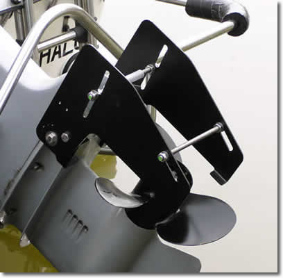
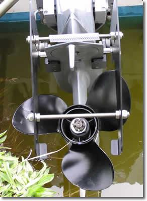
Following a discussion on our forum regarding directional stability with outboards, we decided to publish this gallery entry for anyone thinking about 'rudder attachments'. There are a number of commercial products available, (some no longer produced), and some owners have fabricated their own, on a DIY basis. (member Andy Lawrie has submitted some photos and text on his own project, further down this page.) The most sophisticated commercial product available is the Dutch made 'Ruddersafe' which is suitable for both displacement boats and high speed planing boats. This clever design allows the twin blades to automatically lift up out of the propellor slipstream when the boat is travelling fast, as otherwise they could turn the boat too sharply. At displacement speeds, most outboard boats have rather 'vague' steering, requiring constant minor steering corrections. The addition of a rudder blade behind the prop makes things much more precise, often transforming the handling. Also, when fitted, they give the boat steerage way even with the power 'off' while still moving, unlike most bare outboard legs. The Ruddersafe is available in three sizes (according to the size of boat), and is supplied as a complete set of parts which can be fitted to any make of outboard motor without needing to drill any holes.
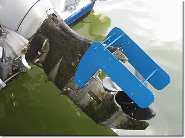
SOA member Andy
Lawrie has made his own DIY rudder blade:
I made up my own version of the Ruddersafe from a few bits of aluminium alloy and stainless steel studding, as shown in the photograph. It has 2 major disadvantages compared to the commercial unit.
Because of these I really recommend buying the commercial unit instead of making your own, but if really want to DIY here are a few observations.
You require 2 pieces of sheet alloy for the hinged vanes, and 2 pieces for the fixed hinge support.
The size and shape of the vanes isn’t critical, mine may be a little smaller than the commercial device, but appears to work OK. They are simple to cut with a saw, using an approx. 8mm drill for the inside corner – you want to avoid sharp corners as these would be a likely point for a stress fracture. Clamp the 2 vanes together and drill 6mm holes for the studs. The positions of the holes is fairly important – the lower ones should be level with the centre line of the prop, the upper ones must be above the engine casting and not touching it in the lowered position. When positioning the top stud, note the comment below about the top stud washers resting on the fixed pieces.
The fixed hinge supports are more difficult for the amateur. They serve 2 purposes – the front carries the hinge bolt, but the entire length of these pieces presses against the inside of the vanes to inhibit sideways movement. The problem is getting a good right angle bend along the whole length of the pieces. You really need a press, but I haven't got one. In the absence of this my only solution is to put them in the vice and bash them with a big hammer, but this doesn’t bend the whole length in one go and it requires some skill and patience to get both sides of the bend quite flat again. I find hammering it on a concrete floor helps to get it flat, but you still really need a bit of finesse with the hammer.
I used 6mm stainless steel pan-heads for the hinges, and to ensure the tightest fit I drilled the holes in all 4 parts undersize and carefully opened them up with a round file.
That’s pretty much it. I cut the 6mm stainless steel studding to length and bolted the 2 sides together, measuring carefully to get them parallel. I placed 3 washers inside each side of the top stud. The edges of these rest on the fixed pieces when in the operating position and stop the studs touching the engine casing.
I attached the vanes to the fixed parts with the pan-heads and stainless steel nylock nuts.
Finally I drilled fixing holes in the fixed parts and in the cavitation plate, gave the whole thing a coat of anti-foul and bolted it on.
The first test found the engine pulling to starboard, so I used a large adjustable spanner to apply a small set to starboard at the lower end of each vane. It doesn’t need much – it is barely perceptible if you look very hard, but it has the desired effect and now steers exactly neutral.
The advantage is
two-fold. a) it does reduce the amount of wandering about and makes
the boat more stable in yaw, and b) course corrections are more predictable
and require less steering input. (Many
thanks to Andy for his kind permssion to include his © photos and
text on this site) |